

TECHNICAL NOTE
Angled Deposition Method for PVDF
Reducing Residual Stress in High-Shrinkage Fluoropolymer Prints
Filasophia R&D | January 2026
Abstract
PVDF (polyvinylidene fluoride) exhibits thermal shrinkage rates that exceed most engineering thermoplastics. When combined with high-adhesion bed systems, this shrinkage generates internal stresses sufficient to deform 1.0mm spring steel build plates or cause adhesive layer failure. This document presents an angled deposition method using tree support structures that allows controlled, uniform shrinkage during cooling. The method has been validated on Bambu Lab X1 Carbon hardware with print speeds between 100 and 200 mm/s.
Problem Statement
Standard horizontal deposition of PVDF creates a mechanical conflict. The adhesive system bonds the first layer to the build surface. As the part cools, PVDF contracts at a rate higher than the adhesive or steel substrate can accommodate. The material cannot slide across the adhesive surface to relieve stress.
Two failure modes result:
Mode A: Plate deformation. Shrinkage forces exceed plate rigidity. The build plate bends upward at corners and edges, even with 1.0mm steel thickness.
Mode B: Adhesive failure. Shrinkage forces exceed adhesive bond strength. The adhesive layer tears or delaminates, releasing the part mid-print or causing localized warping.
Methodology
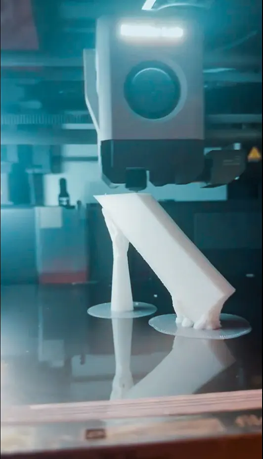
The angled deposition method reduces contact area between the part and the adhesive surface while maintaining print stability. The part is rotated 45 degrees on the XZ or YZ plane, supported by tree-type structures with expanded bases.
Mechanism
Tree supports contact the bed through small circular footprints rather than the full part geometry. During cooling, the part contracts uniformly in three dimensions. The support structures flex slightly, absorbing stress that would otherwise transfer to the build plate. Residual stress within the finished part is reduced because shrinkage occurs symmetrically rather than being constrained on one axis.
Process Parameters
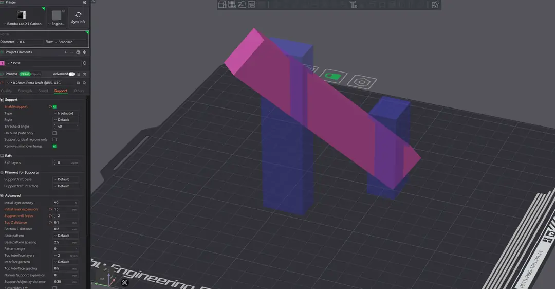
The following parameters were validated on Bambu Lab X1 Carbon using Bambu Studio slicer:
| Part Orientation | 45° rotation on XZ or YZ plane |
| Support Type | Tree (automatic generation) |
| Support Wall Loops | 2 |
| Top Z Distance | 0.1 mm |
| Bottom Z Distance | 0.2 mm |
| Initial Layer Expansion (Support) | 15 mm |
| Support Enforcers | Manual placement as required |
| Cooling Fan | 15% |
| Print Speed | 100 to 200 mm/s |
Parameter Notes
Top Z Distance: Set to half the layer height (0.1mm for 0.2mm layers). This gap allows support separation without damaging the part surface.
Initial Layer Expansion: 15mm expansion creates wider support bases, increasing bed contact area for stability during the print while keeping the expansion localized to support structures only.
Support Wall Loops: Two perimeter loops provide sufficient rigidity to support angled geometry without excessive material use.
Fan Speed: Reduced to 15% to slow the cooling rate. Slower cooling reduces the thermal gradient across the part, allowing more gradual stress relief.
Results
The angled deposition method was tested across multiple geometries and print durations. Observations:
No measurable plate deformation after cooling to ambient temperature.
No adhesive layer damage or tearing.
Parts released cleanly with standard release spray application.
The method has also been validated on PA (nylon), PC (polycarbonate), and carbon-fiber reinforced variants with similar results.
PVDF-Specific Observations
Unlike other tested materials, PVDF prints exhibited localized dimensional instability at support interface zones. This manifests as minor surface irregularity where tree support structures contact the part geometry. The effect is attributed to PVDF's higher shrinkage coefficient creating differential cooling stresses at support contact points.
The overall print geometry and structural integrity remain acceptable. However, for applications requiring tight tolerances at support interface surfaces, parameter optimization is recommended.
Optimization Recommendations
The following parameter adjustments may reduce dimensional instability at support interfaces: Reduce support contact area. Decrease the surface area where tree supports meet the part. This reduces thermal bridging and localized stress concentration.
Reduce support wall loops to 1. Thinner support structures flex more readily during cooling, reducing force transfer to the part surface.
Increase top Z distance. A larger gap between support tips and part surface reduces thermal coupling and allows easier separation.
These parameters interact with each other and with part geometry. Iterative testing on representative geometries is recommended to establish optimal settings for specific applications.
Conclusion
Angled deposition with tree supports provides a viable path for printing high-shrinkage fluoropolymers on open-frame FDM systems. The method decouples adhesive performance from part geometry, allowing the adhesive to maintain bed contact while the part contracts freely during cooling.
For geometries where 45-degree orientation is not feasible, support enforcer placement may require manual adjustment. Contact Filasophia technical support for application-specific guidance.